I-V Curve Testing Kits: Essential Tool for PV Module Health and Performance Analysis
I-V Curve Testing Kits: Essential Tool for PV Module Health and Performance Analysis
Introduction
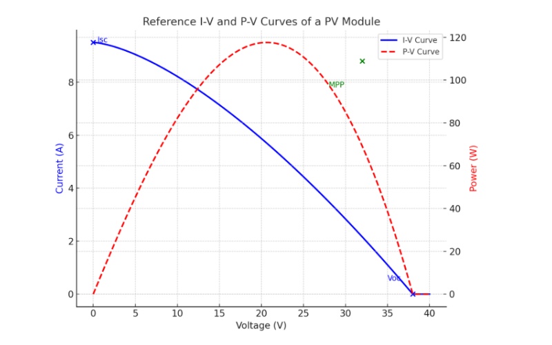
An I-V curve testing kit is often described as the “ECG machine” for photovoltaic (PV) modules and strings. Just as an electrocardiogram reveals the condition of the human heart, the I-V curve provides a clear picture of a solar panel’s health and performance. By recording the relationship between current (I) and voltage (V), the tester helps operators identify efficiency levels, detect faults, and monitor the long-term reliability of solar power plants.
Functions of an I-V Curve Testing Kit
The I-V curve tester performs multiple critical measurements in real-world solar conditions:
> Voltage and current of PV modules or strings
> Solar irradiance using a reference sensor
> Module and ambient temperature via temperature probes
> DC apparent power calculation
> Graphical I-V and P-V curve plotting for intuitive analysis
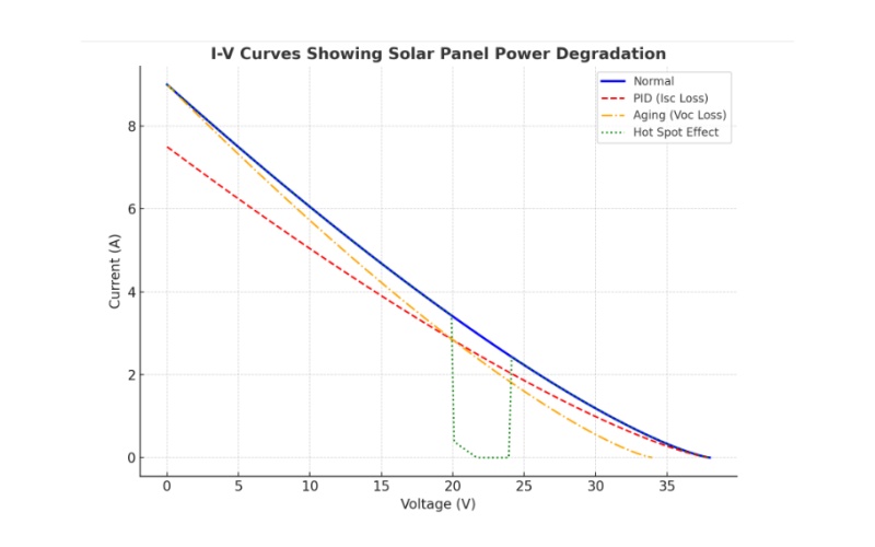
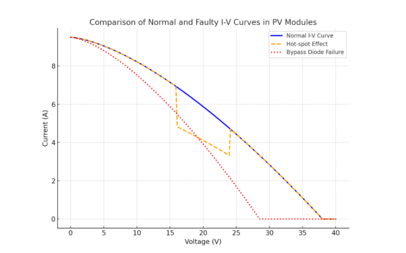
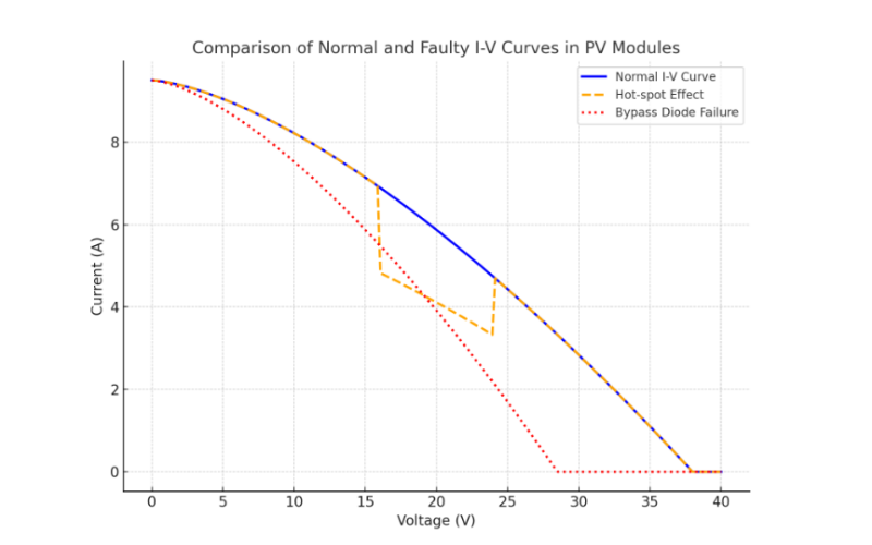
> Fault detection such as shading, aging, hot spots, wiring errors, or bypass diode failures
> STC (Standard Test Condition) conversion to normalize results for comparison
Structure of a Portable I-V Curve Testing Kit
Component | Description |
Main Housing | Portable, dust- and splash-proof design |
Display Screen | Color LCD (some with touchscreen), shows I-V/P-V curves and parameters (Isc, Voc, Pmax) |
Control Keys | Function, navigation, and power keys for easy operation |
Sensors | Irradiance and temperature sensors for accurate environment measurement |
Connection Parts | Test leads with four-wire method for accuracy; safety isolation switches on some models |
Internal Circuit & Software | High-speed data acquisition and analysis, built-in STC conversion |
Working Principle
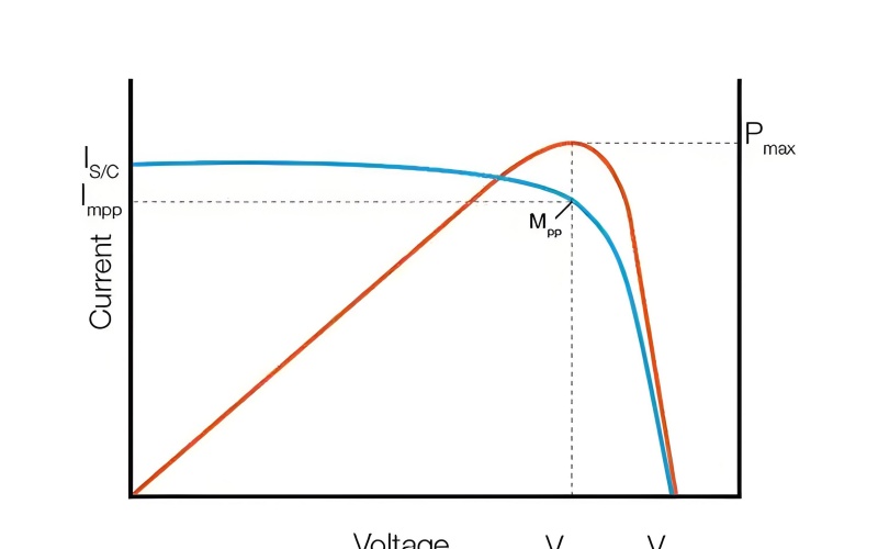
> The tester applies the dynamic load method by charging and discharging an internal capacitor:
1. At the start, the capacitor is empty (short-circuit state), giving the short-circuit current (Isc).
2. As the capacitor charges, voltage rises while current decreases.
3. When fully charged, current drops to zero, and voltage reaches open-circuit voltage (Voc).
4. The tester captures these changes at high speed, producing a smooth I-V curve.
> > Faults appear as distortions:
Hot spot effect → step-shaped dip in the curve
Bypass diode failure → sudden voltage drop
Mismatch between modules → multiple curve branches
Testing Procedure

Operating an I-V curve tester is highly automated:
1. Mount irradiance and temperature sensors on the PV module.
2. Connect test leads to the module or string (color-coded for safety).
3. Power on the device; it self-checks and calibrates within ~15 seconds.
4. Input module specifications or select from the internal database.
5. Start the test. The charging cycle lasts 10–30 seconds, depending on module power.
6. The screen displays I-V and P-V curves, and calculates key parameters: Isc, Voc, Pmax.
7. Save the data. Results can be exported via USB, wireless transfer, or synchronized to the cloud for long-term monitoring.
Conclusion
I-V curve testing kits are indispensable for solar power plant operation and maintenance. They enable accurate fault detection, performance analysis, and long-term monitoring of PV systems. By converting field measurements into STC-based results, these instruments provide reliable data across different times and locations, ensuring efficiency and maximizing energy yield. More information, please contact us!